Después de saber como funciona el registro de desplazamiento 74HC595, vamos con el primer tutorial (pero no el último) sobre él. Vamos a hacer un contador de 8 bits con el IC 74HC595, su función es bien simple, contar de 0 a 255 pero en lugar de usar 8 pins de salida usaremos 3 que son lo que necesitamos para controlar el IC 74HC595.
Necesitamos:
1 Placa Arduino Uno
1 Protoboard
8 LEDs
8 Resistencias de 220Ω
1 Registro de desplazamiento 74HC595
Cables para realizar las conexiones
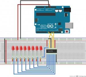
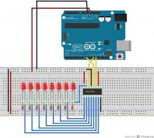
Lo primero que haremos sera colocar los 8 LEDs con las 8 resistencias en sus cátodos (yo en el video uso resistencias de 1kΩ porque no tengo de 220Ω), y luego colocamos el registro de desplazamiento, cuidado con la mueca que tiene, fijaos en la orientación a la hora de ponerle las conexiones o lo podeis quemar.
De la patilla 1 a la 7 conectamos 7 de nuestros LEDs y la patilla 15 la conectamos al 8º (la patilla 15 al que esté más a la derecha, el menos significativo, la patilla 1 al segundo…..). Las patillas 8 y 13 van a tierra de la protoboard, las patillas 10 y 16 van a 5V de la protoboard, la patilla 11 (reloj) va al pin 12 de nuestra placa, la 12 (latch) va al pin 8 y la 14 (datos) va al pin 11. Ahora conectamos 5V de nuestra placa a la protoboard y GND de nuestra placa a la protoboard.

Código fuente:
//Pin de Latch 74HC595
int latchPin = 8;
//Pin de Reloj 74HC595
int clockPin = 12;
//Pin de Datos  74HC595
int dataPin = 11;


void setup() {

  pinMode(latchPin, OUTPUT);
  pinMode(clockPin, OUTPUT);
  pinMode(dataPin, OUTPUT);
}

void loop() {
  // Contamos de 0 a 255
  // Encendido de los Leds
  for (int numberToDisplay = 0; numberToDisplay < 256; numberToDisplay++) {
    // Ponemos el pin de Latch a low
    // así los LEDs no cambian mientras enviamos los bits:
    digitalWrite(latchPin, LOW);
    // desplazamos los bits:
    shiftOut(dataPin, clockPin, MSBFIRST, numberToDisplay);

    //ponemos a hig el pin de Latch así se encienden los LEDs:
    digitalWrite(latchPin, HIGH);
    // pasusa:
    delay(200);
  }
}
Vamos a explicar el código, declaramos 3 variables para los 3 pins que vamos a necesitar y en el void setup() las delcaramos como salida. En el void loop() declaramos un for que irá de 0 a 255, en el cual vamos incrementando la variable que se mostrará por el IC 74HC595 para encender los LEDs. Primeramente ponemos el pin de latch a LOW, así los LEDs no cambian mientras enviamos los bits, después le pasamos el dato a mostrar y desplazamos los bits, ponemos el pin latch a HIGH para encender los LEDs y le damos un retardo para ver como va haciendo la cuenta.
style="display:inline-block;width:728px;height:15px"
data-ad-client="ca-pub-3868159888315364"
data-ad-slot="7639712738">
After knowing how the shift register 74HC595 works , let’s go with the first tutorial (but not the last) about it. Let’s make an 8-bit counter with IC 74HC595 , its function is very simple , counting from 0 to 255 but instead using 8 output pins, we use 3, which are what we need to control the 74HC595 IC .
We need :
1 Plate Arduino Uno
1 Breadboard
8 LEDs
8 220Ω resistors
1 74HC595 Shift Register
Cables for connections
The first thing we will do is to place the 8 LEDs with 8 resistors in their cathodes ( i use 1kΩ resistors in the video because I haven’t 220Ω resistors) , and then place the shift register, watch the grin that has , look at the guidance when putting the connections or you can burn it.
We connect leg 1 to 7 to 7 LEDs and connect leg 15 to the 8th ( leg 15 which is further to the right , the least significant , the second to leg 1…..). Legs 8 and 13 are grounded in the breadboard , the legs 10 and 16 are connected to 5V breadboard lane, leg 11 (clock ) goes to pin 12 of our plate , leg 12 (latch) goes to pin 8 and leg 14 (data) goes to pin 11. Now we connect our board 5V and GND pins to the breadboard.

Source code:
//Pin de Latch 74HC595
int latchPin = 8;
//Pin de Reloj 74HC595
int clockPin = 12;
//Pin de Datos  74HC595
int dataPin = 11;


void setup() {

  pinMode(latchPin, OUTPUT);
  pinMode(clockPin, OUTPUT);
  pinMode(dataPin, OUTPUT);
}

void loop() {
  // Contamos de 0 a 255
  // Encendido de los Leds
  for (int numberToDisplay = 0; numberToDisplay < 256; numberToDisplay++) {
    // Ponemos el pin de Latch a low
    // así los LEDs no cambian mientras enviamos los bits:
    digitalWrite(latchPin, LOW);
    // desplazamos los bits:
    shiftOut(dataPin, clockPin, MSBFIRST, numberToDisplay);

    //ponemos a hig el pin de Latch así se encienden los LEDs:
    digitalWrite(latchPin, HIGH);
    // pasusa:
    delay(200);
  }
}
Let’s explain the code, Let’s explain the code , we declare three variables for the 3 pins that we will need and in void setup () we configure them as output. In void loop () we declare a for loop that will go from 0 to 255 , which will increase the variable to be displayed by the 74HC595 IC to power the LEDs. First we put the pin latch to LOW so the LEDs do not change while we send the bits, after we pass the data to display and move the bits, and we put the latch pin to HIGH to turn on the LEDs and give to the board a delay to see how it goes counting.
style="display:inline-block;width:728px;height:15px"
data-ad-client="ca-pub-3868159888315364"
data-ad-slot="7639712738">

