En este post vamos a ver cómo construir un sistema de domótica basado en SMS con 5 canales utilizando la placa 1sheeld.Ademas en lugar de usar relés electromagnéticos el autor ha construido su placa SSRs utilizando triacs con indicación LED a pesar de que este tipo de placas se pueden encontrar fácilmente disponibles.
Si sabe de Arduino y sus escudos con GSM y WIFI, sabrá que hoy por hoy son muy caros. Para sustituirlos con sólo uno, los inventores egipcios de 1Sheeld han hecho un escudo único maravilloso que se conecta a su teléfono inteligente android vía Bluetooth y utiliza todos los sensores y conectividad de él. También puede utilizar más de un escudo en un momento como GSM, WIFI, acelerómetro, giroscopio etc..
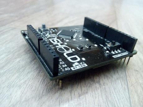
Para este montaje necesitara:
- 1sheeld( http://www.1sheeld.com/)
- Arduino (Mega o Uno pero cada arduino debe funcionar)
- Cable del USB
- Fuente de alimentación USB (opcional)
- Un ordenador portátil o PC al programa arduino
- Instalar IDE de Arduino
- Una caja de plástico o usted puede hacer una de acrílico
- Rrelés (puede hacer su propia SSR )o un circuito controlador si no está utilizando el módulo de relés casero
Para empezar tendría que colocar la placa 1Sheld sobre su Arduino. Observe que debe colocar 1shield haciendo coincidir los pines de Arduino con los de la placa 1Shiled tal y como aparece en la fotografía de mas abajo :
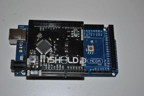
Como se observa .,tiene que tener mucho cuidado colocando correctamente tu 1sheeld sobre todo durante el uso con Arduino Mega.
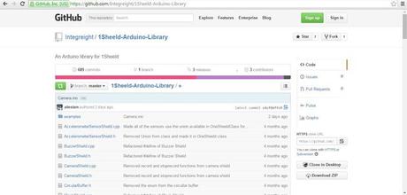
Descargar 1sheeld library
Tiene que descargar y colocar 1sheeld biblioteca desde aquí –https://github.com/Integreight/1Sheeld-Arduino-Lib…
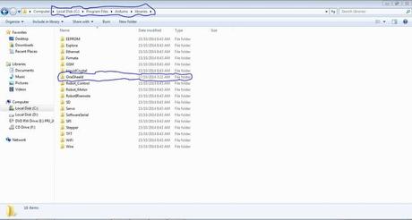
Y luego extraer a la ubicación en las bibliotecas de arduino
El código
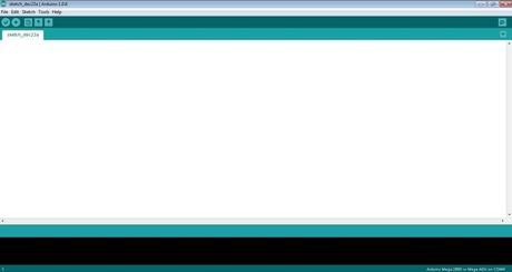
Abierto arduino IDE luego puede copiar , pegar este código y luego subir.
Logicamente ,en lugar de +1234567890 en el programa deberá añadir el número de teléfono con código del país de que el mensaje llegará a su teléfono
Hay cinco pines-13,12,11,10,9. de modo que si quiere encender y apagar el pin 13, entonces tiene que enviar el mensaje “on13” para encender y “off13″ para fuera.
También puede enviar el mensaje “FOR ALL” o “off” para activar o desactivar los cinco en un mismo instante
Y usted puede haber notado que programa 1sheeld es más fácil que escudo GSM para el mismo proyecto de programación.
A continuación se describe el código fuente empleado
// Programmer: Tanishq Jaiswal
// Email: [email protected]
// Age: 15
// Library: OneSheeld
// Shield: 1sheeld (
 www.1sheeld.com   )
    /*
    A simpleExamplewhichwillturnthepinsonandoffwhilerecievingspecificmessagesfromspecificphone.
    5pinswhich areusedhere pin: 13,12,11,10 and 9.

    */
/* Include 1Sheeld Library */
#include
int ledPin13 =13 ; /* led on pin 13 for debuging */
int ledPin12 =12; /* led on pin 12 for debuging */
int ledPin11 =11; /* led on pin 11 for debuging */
int ledPin10 =10; /* led on pin 10 for debuging */
int ledPin9 =9; /* led on pin 9 for debuging */
int ledpin =4; /* led on pin 4 for debuging */
void setup()
{
/* Start communication */
OneSheeld.begin();
/* This function invokeds receiveSms once any new messages are
received */
SMS.setOnSmsReceive(receiveSms);
}
/* Nothing to loop on */
void loop()
{}
/* Receiving Function for new SMS’s */
void receiveSms(const char * number ,const char * text)
{
if(!strcmp(number,”+1234567890″)) /* phone number from which you will send the sms “PUT YOURS IN PLACE OF +1234567890″ */
{
if(!strcmp(text,”on13″)) /* Check if i need to open the light connected to (pin 13)*/
{
digitalWrite(ledPin13,HIGH); /* turn on the light (pin 13) */
}
if(!strcmp(text,”off13″))
{
digitalWrite(ledPin13,LOW); /* turn off the light(pin 13) */
}
if(!strcmp(text,”on12″)) /* Check if i need to open the light (pin 12) */
{
digitalWrite(ledPin12,HIGH); /* turn on the light (pin 12) */
}
if(!strcmp(text,”off12″))
{
digitalWrite(ledPin12,LOW); /* turn off the light(pin 12) */
}
if(!strcmp(text,”on11″)) /* Check if i need to open the light (pin 11) */
{
digitalWrite(ledPin11,HIGH); /* turn on the light (pin 11) */
}
if(!strcmp(text,”off11″))
{
digitalWrite(ledPin11,LOW); /* turn off the light(pin 11) */
}
if(!strcmp(text,”on10″)) /* Check if i need to open the light (pin 10) */
{
digitalWrite(ledPin10,HIGH); /* turn on the light (pin 10) */
}
if(!strcmp(text,”off10″))
{
digitalWrite(ledPin10,LOW); /* turn off the light(pin 10) */
}
if(!strcmp(text,”on9″)) /* Check if i need to open the light (pin 9) */
{
digitalWrite(ledPin9,HIGH); /* turn on the light (pin 9) */
}
if(!strcmp(text,”off9″))
{
digitalWrite(ledPin9,LOW); /* turn off the light(pin 9) */
}
if(!strcmp(text,”on all”))
{
digitalWrite(ledPin9,HIGH); /* turn on the light(pin 9) */
digitalWrite(ledPin10,HIGH); /* turn on the light(pin 9) */
digitalWrite(ledPin11,HIGH); /* turn on the light(pin 9) */
digitalWrite(ledPin12,HIGH); /* turn on the light(pin 9) */
digitalWrite(ledPin13,HIGH); /* turn on the light(pin 9) */
}
if(!strcmp(text,”off all”))
{
digitalWrite(ledPin9,LOW); /* turn off the light(pin 9) */
digitalWrite(ledPin10,LOW); /* turn off the light(pin 9) */
digitalWrite(ledPin11,LOW); /* turn off the light(pin 9) */
digitalWrite(ledPin12,LOW); /* turn off the light(pin 9) */
digitalWrite(ledPin13,LOW); /* turn off the light(pin 9) */
}
else
{
digitalWrite(ledpin,LOW); /* put any unused pin here (pin 4) */
}
}
}
Ahora todo lo que necesita hacer es subir el código a su arduino y una vez que se carga saltar al siguiente paso.
Descargar la aplicación 1sheeld
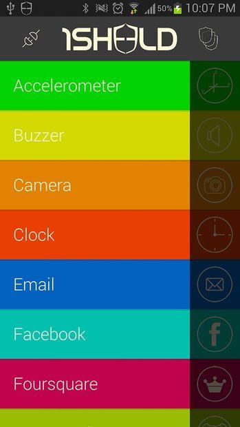
Debe descargar desde Playstore la apliacion 1sheeld.Tras instalarla, abrala y luego encienda el Bluetooth, conectar a la 1sheeld y luego seleccione el escudo de SMS y con esto su Arduino ya estará preparado para recibir los comandos via SMS.
En cuanto a la utilización de los cinco pines-13,12,11,10,9 bien puede adquirir un circuito de potencia ( via triac o reles ) o puede hacerse su propio circuito controlador usando los transistores NPN 2n2222 atacando relés (de hecho la placa y el circuito se está realizando en el PCB Express y el enlace es aquí.)
Nota: Si no tiene experiencia de trabajo con alto voltaje entonces debería usar leds en lugar de cualquier aparato de alto voltaje. NO SOY RESPONSABLE SI SE DAÑa USTED O A SU PROPIEDAD, UTILICE LAS PRECAUCIONES ADECUADAS Y DESENCHUFE TODO INCLUSO ANTES DE ESTAR CERCA DE ÉL.
Fuente aqui


